Welcome Back to the Networking Saga – Part 2! 🎉
Guess who’s back for more packets, protocols, and maybe a little bit of pain? Yep, it’s time for Part 2 of our networking journey!After getting through the first part like true tech heroes, I finally found some time (and energy) to sit down and write the next bit.
So grab your chair, a cup of coffee, and maybe a snack—because we’re about to peel back another layer of this networking onion. Warning: there might be a few tears… from confusion or laughter. 😄Don’t get me wrong—I still love networking. But let’s be honest, even cool topics can feel a bit boring when you’re drowning in acronyms and diagrams.
So let’s keep it light, have some fun, and make this networking stuff a little less painful. Ready? Let’s go!
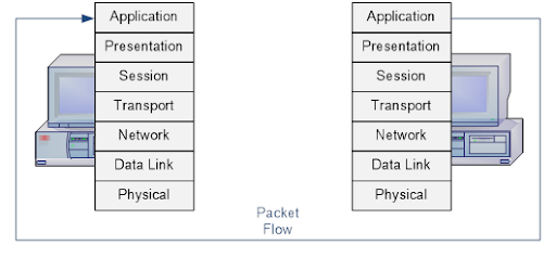
5. Network Layer (Layer 3)
What happens
- IP Addressing: The network layer encapsulates TCP segments into IP packets, adding source and destination IP addresses (e.g., your device’s IP and 93.184.216.34).
- Routing: The packet is routed through the internet:
- Your device sends the packet to the default gateway (your router).
- The router uses its routing table to forward the packet toward the destination IP, potentially through multiple routers.
- Routers use protocols like BGP or OSPF to determine the best path.
- Output: IP packets are passed to the data link layer.
Lets discuss about TCP segment structure
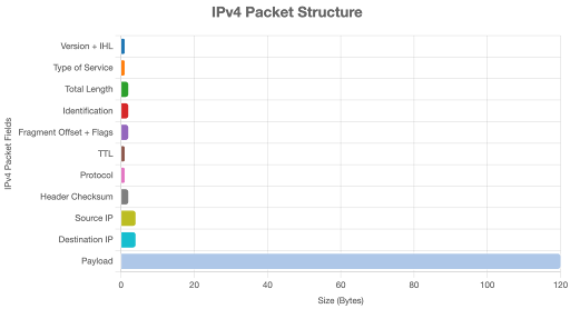
Structure of an IPv4 Packet (IPv6 is similar but with differences noted):
- Header (20-60 bytes, typically 20 bytes without options):
- Version (4 bits): Indicates IPv4 (4) or IPv6 (6).
- Internet Header Length (IHL) (4 bits): Specifies header length (in 32-bit words).
- Type of Service (ToS) (1 byte): Sets priority or QoS (e.g., low delay).
- Total Length (2 bytes): Size of the packet (header + payload, max 65,535 bytes).
- Identification (2 bytes): Tags fragments of the same packet for reassembly.
- Fragment Offset (13 bits): Indicates the position of a fragment in the original data.
- Time to Live (TTL) (1 byte): Limits packet lifetime to prevent loops (e.g., 64 hops).
- Protocol (1 byte): Identifies the encapsulated protocol (e.g., 6 for TCP).
- Header Checksum (2 bytes): Ensures header integrity.
- Source IP Address (4 bytes): Sender’s IP (e.g., your device’s IP).
- Destination IP Address (4 bytes): Receiver’s IP (e.g., 93.184.216.34 for example.com).
- Options (0-40 bytes, optional): Rarely used, for features like routing.
- Payload: Contains the TCP segment (header + data).
6. Data Link Layer (Layer 2)
What happens
- Framing: IP packets are encapsulated into data frames, adding layer 2 headers (e.g., Ethernet headers with source and destination MAC addresses).
- ARP (if needed): If the destination IP is on the same local network, the Address Resolution Protocol (ARP) resolves the destination IP to a MAC address.
- Switching: Local switches forward frames based on MAC addresses. If the destination is outside the local network, the frame is sent to the gateway’s MAC address.
- Output: Frames are passed to the physical layer.
Let’s talk about frame structure:
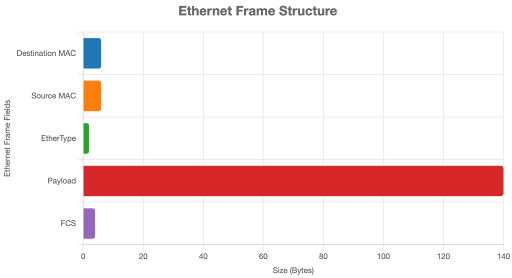
Structure of an Ethernet Frame (most common for wired networks):
- Header (14-18 bytes):
- Preamble (7 bytes): Synchronizes sender and receiver (not always counted in frame size).
- Start Frame Delimiter (SFD) (1 byte): Marks the frame’s start.
- Destination MAC Address (6 bytes): Hardware address of the next hop (e.g., router’s MAC).
- Source MAC Address (6 bytes): Sender’s hardware address (e.g., your device’s NIC).
- EtherType (2 bytes): Indicates the protocol of the payload (e.g., 0x0800 for IPv4, 0x86DD for IPv6).
- VLAN Tag (4 bytes, optional): Used in VLAN-enabled networks for tagging.
- Payload (46-1500 bytes): Contains the IP packet. If the packet is smaller than 46 bytes, padding is added.
- Frame Check Sequence (FCS) (4 bytes): A CRC checksum to detect transmission errors.
7. Physical Layer (Layer 1)
What Happens
- Signal Transmission: Frames are converted into electrical signals, optical signals, or radio waves, depending on the medium (e.g., Ethernet cables, Wi-Fi, fiber optics).
- Hardware: Network interface cards (NICs), cables, or wireless antennas transmit the signals to the next device (e.g., router or switch).
- Propagation: The signals travel through the physical medium, potentially across multiple networks, until they reach the destination server.
Server-Side Processing
- Physical to Application: The server receives the signals, and the process reverses:
- Physical Layer: Converts signals to frames.
- Data Link Layer: Strips off layer 2 headers, passing packets to the network layer.
- Network Layer: Routes packets internally, removing IP headers.
- Transport Layer: Reassembles TCP segments into the HTTP request, ensuring no data loss.
- Application Layer: The server’s web server (e.g., Apache, Nginx) processes the HTTP request, retrieves the requested resource (e.g., index.html), and constructs an HTTP response (e.g., HTTP/1.1 200 OK with HTML content).
- TLS (for HTTPS): The response is encrypted if HTTPS is used.
Response Journey (Back to Client)
- Application to Physical: The server sends the response back through the layers:
- Application Layer: HTTP response is created and passed to the transport layer.
- Transport Layer: TCP segments the response, assigns ports, and ensures reliable delivery.
- Network Layer: IP packets are formed and routed back to your device’s IP.
- Data Link Layer: Frames are created and sent through switches/routers.
- Physical Layer: Signals are transmitted back to your device.
- Client Processing:
- Your device reverses the process, from physical to application layers.
- The browser receives the HTTP response, renders the HTML, and may initiate additional requests for resources (e.g., CSS, JavaScript, images).
And that’s the end of Part 2! 🎉
If you’ve made it this far without falling asleep or throwing your laptop—well done! We’ve covered another piece of the big networking puzzle.
Thanks for sticking with me through the nerdy stuff. I promise, it gets better (or at least more interesting) as we go.